Tape Library Setup
Introduction to Tape Library Setup
Catalogic DPX is designed with comprehensive tape library support in mind.
Tape library setup involves two major procedures: installation and configuration. Each of these procedures is described below.
Tape Library installation entails creating the media changer device file needed to enable communication between DPX and the tape library media changer.
Tape Library configuration entails defining the tape library properties so DPX can back up to and restore from media (tapes) accessible to the tape library.
See also. For the latest system compatibility details regarding supported hardware, file systems, applications, operating systems, and service packs, see DPX 4.11 Compatibility Matrix.
For more information about tape libraries in the NetApp environment, read knowledge base article 46357 – Configuring Tape Library Connected to NetApp Appliance.
Tape Library Pre-Setup
Before beginning the tape library setup process, use the Detect utility to ensure DPX can communicate with the medium changer and that the medium changer status is zero.
The recommended starting point is Unknown Medium Changer disabled, which displays in the Windows Device Manager. If Detect can communicate with the medium changer, the status is zero. For each Detect attempt, the goal is to validate that Detect can see a medium changer and that the status is zero. If those states are not displayed, make a change and run Detect again.
Prepare to use Detect
Ensure the following conditions are met before using Detect:
SCSI support and tape drive support are enabled on the operating system. Physically connect each tape library to its controller node and device servers. You can do this directly or through a SAN.
The tape device drivers, which are supplied by tape drive manufacturers, are properly installed. Drivers are often available from the manufacturer’s website. Additionally:
Drivers are compatible with the operating system of the device server. Consult the documentation provided by your hardware vendor.
Tape drivers are capable of writing in variable block size mode.
On Windows platforms, tape drives are visible in Device Manager and the drives are enabled.
DPX client software is installed on controller nodes and device servers. Client software is installed on the master server by default.
For controller nodes, the media changer is not claimed by the operating system or any other software. The media changer must be available for DPX to claim.
The media changer device is disabled in the Device Manager. On Windows Server, the media changer is usually displayed in Device Manager as an Unknown Medium Changer.
To disable the media changer:
Use either of the following methods to navigate to Device Manager:
Click Start > Settings > Control Panel > Administrative Tools > Computer Management > Device Manager.
Right-click My Computer, then select Properties > Hardware > Device Manager.
Right-click on the media changer (usually Unknown Medium Changer). Select Disable.
If you see the message Disabling this device will cause it to stop functioning. Do you want to disable? Select Yes.
Note that disabling the device does not cause the tape library to stop functioning; rather, it removes control of the device by Windows. This enables DPX to claim, detect, and control the device.
Run Detect
Use the Detect utility to validate the status of the medium changer before using the DPX Device Control Wizard. For UNIX and Linux environments, run ./bin/bexenv before running the Detect utility.
To run Detect to validate medium changer status:
On the Controller node, click Start > All Programs > DPX Command Prompt (Run as Administrator).
Tip. You can also log in to the Controller node via SSH.
From the DPX command prompt, navigate to <product-directory>\bin\JB.
Run detect -i.
The expected result is Device ID \\.\sync_sa# and status 0.
If the expected result is displayed, go to step 6.
If the expected result does not display, enable the Unknown Medium Changer and proceed to the next step.
Run detect -i again.
The expected result is Device ID \\.\sync_sa# and status 0.
If the expected result is displayed, go to step 6.
If the expected result does not display, install the hardware manufacturer driver for the arm of the tape library. This resolves the Device ID and status of the Medium Changer. Proceed to the next step.
Run detect -i again.
The expected result is Device ID \\.\Changer# and status 0.
If the expected result is displayed, go to step 6.
If the expected result does not display, contact Catalogic Software Data Protection Technical Support.
If you have not already defined your Enterprise, do it now.
Add controller nodes and device servers to your Enterprise.
Device Configuration Wizard
This section is intended for system administrators who are setting up their tape libraries by using Automatic Setup (Process A). If you are setting up your tape library by using Manual Setup (Process B), proceed to Device Detection.
The DPX Device Configuration Wizard allows you to bypass many of the manual steps otherwise required for setting up tape libraries.
When possible, the Device Configuration Wizard generates, maps and names device drivers for each tape drive and tape library media changer. It then adds the tape libraries and tape drives to the Enterprise.
You can apply the Device Configuration Wizard to an existing installation. If you do, the Device Configuration Wizard may update those devices for which it detects a Unique ID, which is the unique identifier assigned to a device by the vendor or agency, usually the device’s serial number.
Platform Considerations
The Device Configuration Wizard is supported by any DPX client running an operating system supported for DPX device servers. An exception is Linux OES, which does not support the wizard.
Tape libraries on platforms that do not support the Device Configuration Wizard must be set up manually, using the procedures described in this instruction set.
See also. For the latest system compatibility details regarding supported hardware, file systems, applications, operating systems, and service packs, see the DPX 4.11 Compatibility Matrix.
Devices Not Auto-Configurable
You should be aware of the following caveat before executing the wizard:
The Device Configuration Wizard may set up some, but not all of the tape drives and media changers in your Enterprise. For example, a device (tape drive or media changer) might not be configurable by the wizard if DPX cannot detect a Unique ID for that device.
Any device not completely set up by the Device Configuration Wizard should be set up manually, using the procedures described in the following sections.
Before starting the Device Configuration Wizard, you can determine whether a given device is configurable by the wizard by running “detect -q” from a device server node accessible to the device. The Detect utility is described in detail in Device Detection. The Auto field on the output report produced by Detect indicates whether the device can be set up with Device Configuration Wizard.
Executing the Device Configuration Wizard
Before executing the Device Configuration Wizard, confirm that all pre-setup steps have been completed. The Device Configuration Wizard can be run from any machine that can ping your master server. Set the environmental variable SSICMAPI so that it points to the master server.
For example:
or
Launching the Device Configuration Wizard
To launch the Device Configuration Wizard from Windows:
Click Start > DPX > Device Configuration Wizard
To launch the Device Configuration Wizard from UNIX:
Change to the bin directory under the installation directory. In addition, you may need to set the DISPLAY environment variable to your local host.
Enter ./devconfwizard at the shell prompt.
The Device Configuration Wizard window is launched.
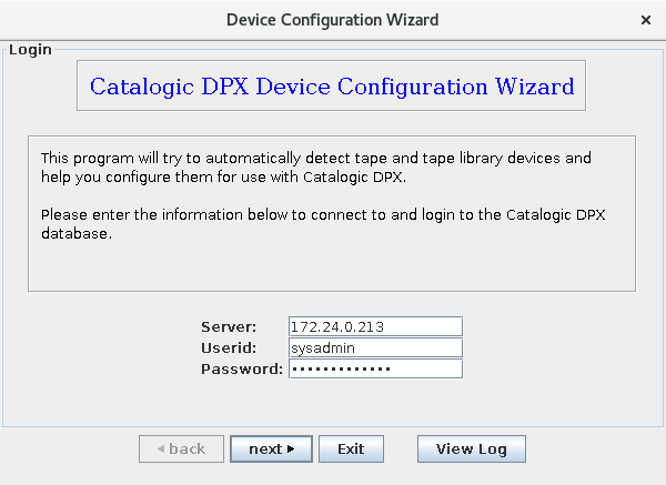
The wizard asks you to log into your Enterprise. Log into the master server as an administrator. After entering your credentials, click next.
Using the Device Configuration Wizard
The Device Configuration Wizard uses an intuitive graphical user interface to guide you through the device configuration process. The wizard probes your Enterprise and detects information about your nodes, devices, tape libraries, and connections.
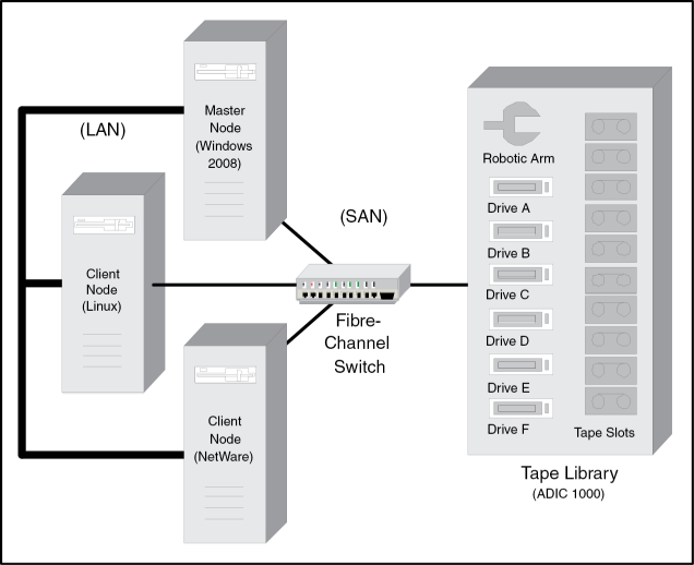
The following is a sample session of the Device Configuration Wizard for illustrative purposes. This sample session sets up a SAN with three heterogeneous servers and one six-drive tape library, as depicted in the following diagram:
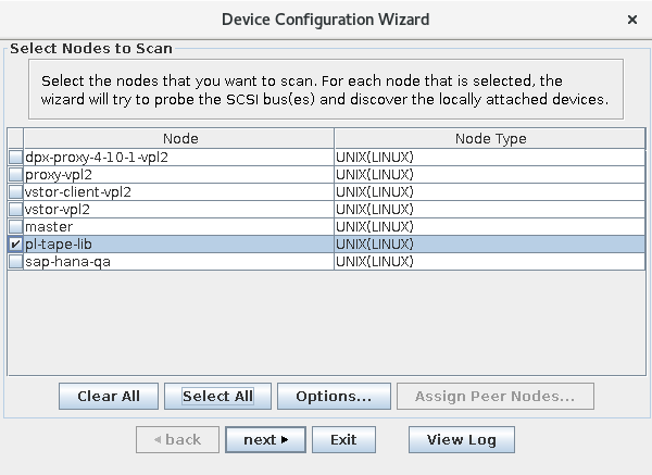
The wizard displays all nodes in the Enterprise that can serve as device controller nodes.
Use the checkboxes to select one or more controller nodes for which you want to install and configure devices.
Clicking the Options… button will display a dialogue box with a list of configurable scan options.
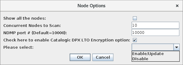
The following options can be adjusted:
Show all the nodes
There may be nodes on the Enterprise whose configuration options indicate they are not compatible with scanning. By default, these nodes are not displayed in the list of potential device controllers. Selecting this option will include those nodes in the list.
Concurrent Nodes to Scan
This setting affects how many nodes the wizard will communicate with concurrently while performing the scan. This can affect scan speed.
NDMP Port NDMP-capable. This setting allows you to set a port number for communicating with NDMP-capable NAS nodes.
Check here to enable Catalogic DPX LTO Encryption Option Clicking this check box will activate the Please Select pull-down menu, which you can use to enable, update or disable LTO hardware encryption functionality. The Enable/Update option enables the encryption option for nodes that support this feature or updates the list of tape devices to which the node can encrypt data.
Click OK to confirm your options choice.
Clicking the Assign Peer Nodes… button displays any other nodes that can communicate with devices in the SAN. (These nodes are not running one of the supported platforms listed at the beginning of this chapter).
When finished configuring options and selecting devices, click next. At this point, the wizard scans the selected node(s) for SCSI devices.
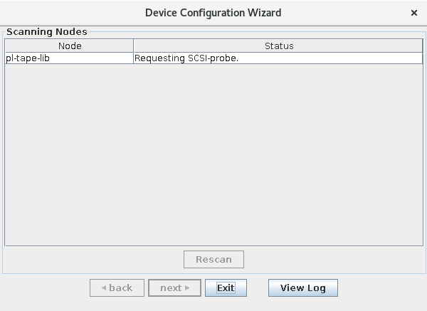
When the nodes have been successfully scanned, “Done” appears in the status column, and the next button becomes enabled. Click next to continue.
The wizard displays all unconfigured tape libraries accessible by the selected nodes. In this example, there is only one tape library, and it is accessible by both nodes. Select the tape library that corresponds to the server (controller node) that will control the media changer. You can either click anywhere in the entry’s row and then click the Add to Enterprise button (which becomes enabled once a selection is made), or you click the entry’s associated check box, which will advance you to the next step without the need to click Add to Enterprise
The wizard requests information about the tape library you selected.
Complete the active fields in the dialog:
Configure As SAN
This check box gives you the option to configure the device as a SAN. The check box appears if the device is seen by only one node. If multiple nodes see the device, it is automatically configured as a SAN and the check box does not appear.
Tape Library Name
Enter a name (up to 14 alphanumeric characters) for the tape library (for example, DEC_TL810). No two tape libraries in the Enterprise can have the same name.
Tape Library Type
Select the tape library type (for example, DEC_TL810) from the pull-down menu. If your tape library type is not shown, select the type that most closely matches yours.
Controller ID
The Device Configuration Wizard generates a media changer device file and installs it on your controller node. The name of that file, assigned by DPX, is displayed in this field.
Data Slots
From the pull-down menu, select the starting and ending slot numbers to use for media volumes. Note that slot numbers start at zero (0). Thus, the first slot is slot number 0, and the final slot is slot number (n-1), where n is the number of slots in your tape library.
Cleaning Slots
From the pull-down menu, select the starting and ending slot numbers to use for cleaning tapes. To configure a single cleaning slot (typical setup), enter the slot number twice. If no cleaning slots exist, leave these fields blank.
Device Type
Select a device type (for example, LTO) from the pull-down menu. All devices in a tape library must be the same type.
Cleaning Threshold
Enter the number of times a drive can be used before it is cleaned.
Comment
Optionally enter an alphanumeric string of up to 48 characters.
When you have filled in all the required information, click next.
The wizard displays a list of devices attached to the newly added tape library. If you need to change the device names, you can do so on this screen. Click inside the device name field and enter a new one.
When you are finished changing device names, click next.
The wizard indicates that the tape library has been added by placing a checkmark in the box in the leftmost column on the New Tape Libraries window. If you have additional tape libraries to add to the Enterprise (in this case we do not), repeat steps 3 through 5 for each.
Note. For a SAN, the tape library needs to be added only once.
Click next when you are finished adding tape libraries. The wizard shows the devices that were added, as well as other detected devices that were not part of a configurable tape library. Use this window to add additional devices, as well as to remove any of the devices added in previous steps.
To add additional listed devices, select a device and click Add to Enterprise, assign the device to a tape library or device pool, then specify a device name. To remove a device you have already added, select the device and click Remove from Enterprise.
Note. If you encounter an error, click View Log. A log file, which can be used for troubleshooting, is displayed. Save the log file by clicking Save….
Click Exit to exit the Device Configuration Wizard.
Later, when you log into the management console and navigate to the Configure Devices window, you can open the device clusters to view all the devices and device paths for a given tape drive.
You can edit the information for any of these devices in the management console under Configure Devices.
See also. Adding a Tape Library.
Device Detection
General Remarks
If you set up your tape library using Manual Setup (Process B), detection is the first step. The DPX Detect utility is also a handy tool for troubleshooting down the road.
The Detect utility allows you to display and map media changers and tape drives accessible from a given device server or controller node. This utility is found in the /bin/JB subdirectory of the main directory.
Detect can be run from any machine on your network under an administrative User ID.
See also. For the latest system compatibility details regarding supported hardware, file systems, applications, operating systems, and service packs, see DPX 4.11 Compatibility Matrix.
If you are using third-party software no longer supported by the vendor, Catalogic Software Data Protection Technical Support may be limited for functions dependent on that software. To address certain issues, the Catalogic Software Data Protection Technical Support may recommend you upgrade the relevant software.
The AIX platform offers limited support, meaning that the configuration phase is not supported and the detection phase may miss some properties such as the World Wide Name or Serial Number. Other platforms offer full support meaning that the Detect utility can detect devices and obtain their vendor ID, product ID, SCSI Target, LUN, etc., plus their World Wide Name and Serial Number. Besides the detection phase, this utility can create (configure) device files.
Some versions of UNIX detect require running in a shell that has the appropriate environment setup. For details contact Catalogic Software Data Protection Technical Support.
The detect -q Utility
You can use either detect -q or detect --query. They are different formats of the same command.
As the first step to every manual tape library installation on the above platforms, you should run the following on your tape library controller node:
detect -q gathers and displays information about media changers and tape drives that are accessible from the node on which you are running Detect. detect -q does not create or install any new devices and does not modify any files. Thus, it is always safe to run Detect with the -q command line option. The following is an example of output from detect -q:
Note that the output contains two tables. The rows in both tables are identified by the Device ID field. The device representing the media changer is identified by Media Changer Device or simply Medium in the Device Type field. So, in the tables above, the third row (\\.\sync_sa0) is the row representing the media changer.
The output displayed above is for a Windows platform, but the content would be similar on any platform. (For Solaris, a freshly connected tape library might not be detected by detect -q, in which case you should use detect -i as described in the next chapter). The following describes the fields (columns) in the output from detect -q, specifically with regard to the media changer device:
Device ID
The file handle of the device driver for this particular device.
Adapter ID
The adapter associated with this device.
BUS
The bus number on this adapter. One adapter may have more than one bus.
Target ID
SCSI Target identifier (SCSI ID).
LUN
Logical Unit Number.
Status
Status values may have different meanings for different platforms. In general, 0 = no problems. Other values are described below, by platform.
For Windows:
-1 Media Changer: device has already been claimed by another driver. Tape Drive: Detect has failed to acquire a handle for device.
-2 Media Changer: Unit attention required. Tape Drive: device is not claimed by a driver and thus is unusable by the OS.
-3 Device will not report unique IDs of its tape drives, but still could be used.
-16 Library may be claimed by a driver on a 64-bit system.
For Solaris:
-3 Device will not report unique IDs of its tape drives, but still could be used.
-5 I/O Error.
-16 Device Busy.
For Linux:
-1 Media Changer: device has not responded properly on a SCSI inquiry command. Tape Drive: drive is not loaded.
-3 Device will not report unique IDs of its tape drives, but still could be used.
For HP-UX:
-1 The media changer or a tape drive has not responded to a SCSI inquiry command.
For AIX:
-1 The media changer or a tape drive failed to open.
Device Type
The type of device, according to SCSI-2 specifications.
String
Vendor and product identification information.
Serial Number/Unique ID
Unique identifier assigned to a device by the vendor or agency (for example, ANSI or SNIA).
World Wide Name
A 64-bit number, assigned by IEEE, used to identify a product. It is often used as a port number on Fibre Channel networks.
DPX Auto
Flag indicating whether the Auto-Configuration utility can be applied to this device.
Note that the Detect output does not have a specific field indicating whether the device is claimed. However, if the appropriate driver does not claim a device, its name will not appear in the Device ID column and -1 will appear in the status column.
More about the Detect Utility
Install Option: Overview
For all platforms listed in the introduction to this topic, you can use detect -i or detect --install, to install the media changer device file. This is discussed in greater detail in Manual Tape Library Installation.
Debug Option
The Detect utility also has a debug option, -d.
For all platforms listed in the introduction to this chapter, there are three debug levels: 1, 2, and 3, with level 3 being the most comprehensive. For example, you can run:
detect -f
The Detect utility -f N options (where N is 1, 2, 3, or 4) allow you to bypass some operations of detect -q.
detect -f 1 processes only media changer devices.
detect -f 2 processes only sequential access devices (tape drives).
detect -f 3 processes media changer and sequential access devices.
detect -f 4 processes only devices that are not changers or tape drives.
Last updated